Common Cutter Baskets Dissected
Willard Says……
What is a cutter basket?
The cutter basket is the “cutting edge” tool that should enable a hydraulic dredge to operate efficiently and productively to accomplish the goals stated in the mission statement below.
Many years ago I began to visit sand and gravel dredge mining operations in order to gain a better understanding of how dredges function. Most of the cutterhead dredges I saw had, when new, been fitted with open cutter baskets formed by five or six curved, spiral-shaped cast steel blades such as seen in the photo, Figure 1. Worn and used as they were when I saw them, they more resembled those shown in the photos, Figures 6 & 7. The modifications came about for good reasons as shall be explained in this paper.
As viewed from the end, a circular steel weldment called a basket is mounted on the end of a rotating shaft. The drive shaft is mounted parallel to, and atop the end of the suction pipe so that the basket covers the suction pipe inlet.
Viewed from the side a basket is usually shaped like an elongated hemisphere. The surface of the basket is formed by the edge of the blades. There are usually five or more blades depending on the diameter of the basket. Each blade is warped and curved with one end welded to the outside of the hub and the other end welded to an open-centered backring. The warped blades give the basket a sort of spiral appearance when viewed from the side.
ROTARY CUTTER MISSION STATEMENT
- Scarify, loosen, stir, rip asunder or otherwise tear free any and all in-situ material found lying in its path.
- Screen out or otherwise prevent passage into the suction inlet of any and all oversize particles.
- Remain open to the passage of slurry whilst partially immersed in a pile of loosened in-situ material.
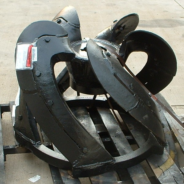
Open-Bladed Basket
PLAIN EDGES
Figure 1
The warped curved blades slice off layers of sticky solids as the basket is forced into the cut. The slicing motion of such blades impose a continuous, more uniform load on the cutter shaft as opposed to higher, cyclic loads that would result if the blades were straight. Like slicing a loaf of bread. It is more easily done with strokes of a serrated blade than by trying to lop off a piece by chopping directly down with a straight-edged knife.
These baskets are effective cutters only when rotated to cause the teeth to point at and dig into the in-situ material. Their digging efficiency diminishes considerably when rotated backwards and their cutting action diminishes to become more like a heavy caress. As can be seen when comparing Figures 1 & 2, right or left had rotation baskets are available. Which is preferable and why I know not.
The cutting edges of smaller bladed baskets may have a jagged tooth-like profile which must be built up by welding or totally replaced when worn out. Larger baskets may have replaceable toothed sheaths that fit over the blades or bolt/weld-on replaceable cutting edges as seen in Figure 2.
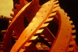
Open-Bladed Basket
Toothed Weld-on Edges
Figure 2
Basket Diameter
It is always desirable to keep the outside diameter of the basket as small as possible yet cover the end of the suction pipe. Some designers squash the end of the suction pipe vertically so that the basket diameter can be made smaller. Assuming the same torque is applied, a smaller diameter basket applies greater force at the digger tooth tips than a larger diameter basket.
The squashed inlet end of the suction pipe is often called a “fish mouth.”
Historically, and still today most new sand and gravel dredges arrive at the pit sporting an open-bladed basket with at least one exception; dredges from Twinkle Co. Years ago open-bladed baskets were referred to as Florida Machine baskets because Florida Machine & Foundry manufactured many, perhaps most of them. Somewhere along the way that company evidently succumbed to economic malnutrition or was gobbled up leaving little trace. Open-bladed baskets are now available from several manufacturers.
Conctractor Dredging
The Florida Machine style of open-bladed basket was designed to deal with the wide variety of materials the contract dredger encounters when cleaning or deepening harbors and channels, maintaining waterways or moving solids that are found to be in the wrong location.
A contractor-type dredge is configured so that it can force its cutter to swing in an arc as it pivots about a spud. A spud is a pipe, located at the rear of the dredge hull, that can be raised and lowered through guides that hold it in a vertical position. In operation, a spud is stabbed into the floor of the waterway where it serves as the center of the arced cut made by the cutter.
Typically, the open-bladed basket is used in a manner similar to that of a milling machine cutter at work shaping wood or metal. The basket, rotating at a relatively high speed, 30 rpm or faster, is lowered into the solids bank to a depth of perhaps half the cutter diameter. It is then crowded sideways and forced to travel in an arc about the spud and forced to cut into the material bank at a controlled rate so that each blade slices off a thin layer of the solids which then flow into the suction inlet. The depth of cut and the speed of swing determine the rate of solids production.
Each successive cutting pass is made incrementally deeper by perhaps half the cutter diameter until the desired depth has been reached. Productive cutting may be possible only while swinging in only one direction in which case the dredge must be swung—deadheaded; not producing—back to the starting point. Once maximum depth is reached, the dredge is advanced a distance perhaps equal to the length of the cutter basket and the procedure is repeated. In theory, the high speed cutting action causes the basket’s blades to slice off a continuous stream of solids that break into pieces small enough to pass through the system without clogging either the basket or the dredge pump.
Sand & Gravel Dredging
Most sand and gravel dredgers cannot profitably use contract dredging procedures and equipment; they must go about mining in a completely different way.
The majority of sand and gravel producers pump solids, comprised mostly of aggregate, to a process plant which functions most efficiently if continuously fed a uniform mixture of particle sizes. A uniform mixture is best obtained if the dredge maintains its suction inlet at the toe of the slope of material where it can take away material, undermine the bank and cause cave-ins. All layers of various-sized particles in the deposit mix together as they cascade to the bottom where they are taken up by the dredge suction.
More often than not, the sand and gravel deposits contain rocks that are too large to pass through the dredge system without plugging. While blockage by oversize particles does not cause mechanical damage, the downtime spent clearing them seriously affects efficiency and productivity—excellent reasons for preventing the oversize from entering the dredge system.
It is astounding how long some dredgers tolerate the repetitious downtime caused by pump plugging before doing something about it. Maybe they are at a loss as to what to do. Or perhaps they simply tolerate the problem and chalk it up as just another difficulty associated with operating a dredge.
Others, less tolerant of downtime and loss of production, attempt to overcome the shortcomings inherent in their open-bladed, swallow-everything-that- comes-along basket. Some of the schemes they have devised to keep oversize out of their dredge systems are described below.
Band-Aid #1: Bar Across The Suction Inlet
Weld a bar or bars across the suction inlet mouth inside the basket to keep oversize rocks from entering the suction pipe. See Figure 3.
This is the cheapest, easiest, least effective solution because it provides no means to automatically eject the oversize rocks once they lodge in, and plug the openings of the suction inlet. Suction plugging awaits only the arrival of two or three oversized particles.
The simplest way to clear the blockage when it does occur, and it will, is to stop the pump, raise the suction and cause backflow from the discharge pipeline to wash the rocks out of the suction openings. Production always ceases when the dredge system is back-washed. The rejected rocks always fall to the bottom. The suction inlet is always let down and repositioned at the bottom where the offending rocks repose. Need I go on?
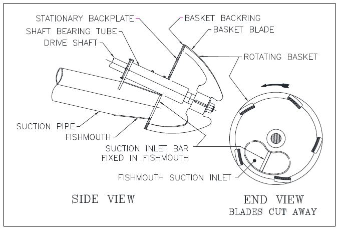
Suction Inlet w/ Bar
Figure 3
What are the odds that those same rocks will once again block the suction? The frustrating cycle of plug and backwash repeats over and over with consequent poor production.
This Band-Aid could be considered somewhat of a success if there are few oversize rocks in the deposit and few instances of suction plugging each day.
Band-Aid#2: The Rock Ring
This is a steel ring welded to the interior of the basket and located so that it continuously bisects the suction inlet opening as it rotates. See Figure 4. The rotating ring prevents oversize rocks from entering the dredge system and automatically removes oversize rocks that may plug the suction inlet.
This idea supposedly works very well when contractor-type swinging procedures are used because the oversize rocks theoretically fall out behind the basket as it traverses the cut. Sand and gravel cutters move only a short distance, remain stationary for a time and then again move only a short distance. A rock ring equipped basket on an essentially stationary sand and gravel dredge will slowly fill up with oversize rocks because there is nowhere for them to go; they cannot exit the basket. Picking up the ladder interrupts production and dumps the rocks out of the basket to fall into the hole where they are likely be glommed up once again when pumping resumes.
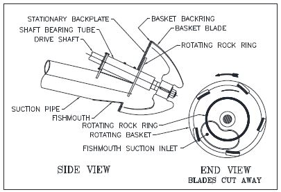
Suction Inlet w/ Rock Ring
Figure 4
The Rock Ring Band-Aid could be considered a success only if the basket seldom plugs with rock. Seldom like twice a day.
Band-Aid #3: The Gatling Plate & Gatling Grid
A steel plate welded inside the backring of the basket containing numerous holes sized to keep unwanted oversize out of the suction inlet. See Figure 5.
The Gatling plate does keep oversize out of the dredge system, and it often does cause the basket to gradually fill with an accumulation of oversize rocks. The oversize rocks linger in the shelter of the basket because they cannot go anywhere else—the same problem that plagues the rock ring Band-Aid.
Another unintended consequence accompanies the use of the Gatling plate. As the pierced plate rotates, its openings pass over the suction inlet and screen out oversize. The openings close as they approach stationary parts of the inlet which creates dozens of pinch points each minute. If a passing rock lodges in one of the closing gaps—pinch-points—one of two things must occur; 1. It is crushed or 2. The cutter stalls. Each such incident—crush or stall— imposes a substantial bending force on the cutter drive shaft. The ceaseless flurry of bending force fatigues the shaft and it ultimately breaks.
Then the whole shebang—Gatling plate, basket and stub-end of the shaft settles in to a place of rest in the cold, dark deep.
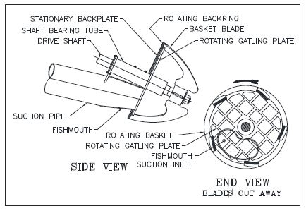
Suction Inlet w/ Gatling Plate
Figure 5
For selfish reasons I am rather fond of the Gatling plate idea because it is good for our business. Every now and then a dredger, weary of buying new cutter shafts and baskets, comes to Twinkle Co for a solution to their problem and buys a more-productive, less-troublesome sifting cutter basket. They then experience the benefits of a cutter that sifts out oversize without plugging or demolishing the cutter shaft on a regular basis.
The Gatling Plate Band-Aid can be called successful as long as the basket does not plug with oversize and the cutter shaft does not break.
Figure 6 shows a “Gatling Grid,” a European version of the Gatling Plate idea that has the merit of eliminating pinch-points. The rotating grid of bars are far enough away from stationary parts to eliminate pinch-points and still prevent oversize from entering the suction inlet. Even so, all of the relatively few grid openings are in the flow path leading to the inlet which makes it likely particles lodging in the grid will be held there by the flow of slurry. Gradual plugging is likely to occur.
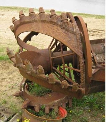 European Gatling Grid
Figure 6
Unintended Consequences
There is yet another reason to dash any hopes that a Gatling Plate Band-Aid will turn an open bladed-basket into useful sifter. In addition to the shortcomings listed above, the Gatling Plate is to blame for causing repetitive, momentary choke-offs of the suction inlet accompanied by resultant blips of dredge pump cavitation. As can be seen in the Figure 5 drawing, the rotating Gatling plate has numerous openings, each sized to prevent entry of oversized rocks into the suction pipe.
When some or all of these few openings simultaneously plug with oversize, flow to the pump is substantially cut off for a fraction of a second until an unobstructed opening revolves into place over the suction inlet. Such momentary stoppages may happen only occasionally on some dredges, however, others experience it more or less continuously.
Regardless of the frequency, choke-off & pump cavitation are always bad news. They should be prevented if at all possible. A Gatling Plate Band-Aid invites these problems.
Band-Aid #4: Grid Bars Between The Blades
See Figures 7 and 8. This fix can be quite successful because it does cause oversize to remain where it belongs—outside the basket at a distance from the suction inlet. Rocks, however, still have a nasty habit of wedging in the openings and staying there, shielded from any jostling action that might tend to eject them. Rotation in the digging direction tends to force them more firmly into their hidy-holes. Reverse rotation will not loosen them because they are sheltered by the projecting blade edges.
If clay is present it will act as mortar and fix the rocks more firmly in place. The basket progressively plugs as more and more rocks take up residence in the grid openings.
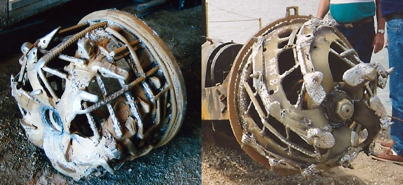 Open-Bladed Basket Open-Bladed Basket
w/Bars Added w/Bars Added
Figure 7 Figure 8
When, once again, sequential plugging has gradually degraded production to an unacceptable rate, the operator must, with reluctance, clear the discharge pipeline, shut the dredge down, journey out to the end of the ladder and hang on with one hand and while perching precariously, use the other hand to laboriously pry the rocks loose and clear the basket. His frustration is compounded by the knowledge that it will not be very long before he has to clean the basket again. And again. Rate of production while clearing the cutter basket? Zero.
This Band-Aid can be successful only if the basket grid openings do not plug with rock and clay.
Conclusion
It is a rare circumstance when an open-bladed basket functions successfully on a sand and gravel dredge without modification. Most fixes are prone to cause problems, with the possible exception of Band-Aid #4—welding bars to form a grid between the blades. This Band-Aid is fairly successful as long as there are only a few oversize rocks and no clay in the deposit.
Twinkle Co offers a wide variety of baskets, many designed to solve specific problems while avoiding the deficiencies of bladed-baskets. See Twinkleco.com
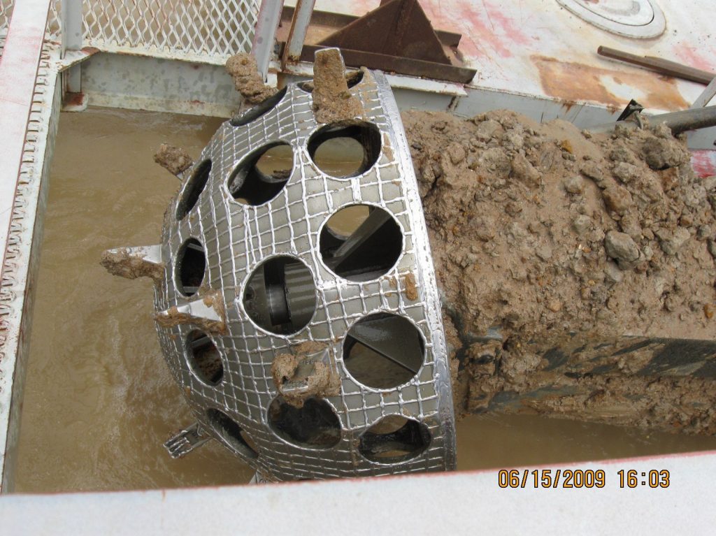
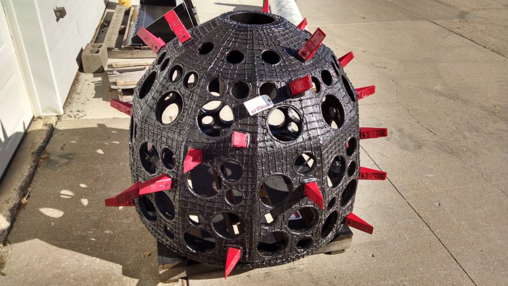
Special notice should be taken of their CLAYMATOR baskets which have proven to be extremely effective in deposits where clay frustrates production using a bladed-basket. Figure 9 shows a CLAYMATOR in action. Figure 10 shows a CLAYMATOR on it’s way to solve a problem.
See other Willardsays papers on baskets and discover one that will eliminate your cutter problems and open the way to increased production.
Contact willard@willardsays.com with questions, comment or criticism.